Fukuoka Institute of Technology
The main mission of the FITSAT-1 is to demonstrate a high speed transmitter module developed by the Fukuoka Institute of Technology. It can send a VGA (640x480pix) resolution jpeg image data at 115.2kbps FSK in 5 to 6 seconds using 5.8GHz ham band. The second mission is to make the satellites twinkles as an ‘artificial star’ using high-output 50 green LEDs in flash mode. This LED light will be observed by small binoculars.
NASA-Catalog: 38853
Downlink
437.445 MHz, 1k2 AFSK AX.25, FM
437.250 MHz, CW beacon, FM
5.840 GHz, 115.2 kBit/s FSK picture transmission
Call
NIWAKA
Status
DECAYED
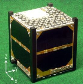
FITSAT-1 is a 10cm cube, and the weight is 1.33kg. The FITSAT-1 body is made by cutting a section of 10cm square aluminum pipe. Both ends of the cut pipe are covered with aluminum plates. The FITSAT-1 electrical power system consists of solar cells, DCDC-converters, single lithium ion battery, three lithium ion batteries connected in series (Hitachi Maxell INR18650PB2, 1450mAH), battery controllers (SII S-8233BAFT, Linear Technology LTC4054-4.2), two deployment switches, and a flight pin switch. Each of these three switches controls electronic switches.
The single lithium ion battery supplies the power for communication and data handling system except high speed communication system and camera. While three batteries in series supply power for experiments of 5.8GHz high speed transmission and flashing LEDs. Each side of the solar cells generates 2.3W (4.74V x 0.487A) of electrical power. The generated power is extracted by maximum power point tracking DCDC-converter and supplied to 5V load, single lithium-ion battery, and three lithium-ion batteries. The charging of the single lithium-ion battery is controlled by a battery protection IC (Liner Technology LTC4054-4.2), and the three lithium-ion batteries are controlled by a battery protection IC (SII: S-8233BAFT). The battery control IC LTC4054-4.2 controls only charging because no over discharge state is assumed. While the battery protection IC S-8233BAFT also controls discharging to protect the three batteries from over consumption of high power experiments. This IC monitors the voltage of each battery cell and controls the charging and discharging.
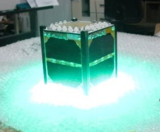
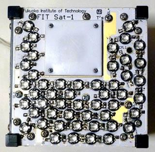
50 green LEDs are attached on the top (+Z plane) of the body. 32 red LEDs are attached on the bottom (-Z plane) of the body. Flashing 50 green LEDs is shown in Figure10. Flashing LEDs has the two modes. One is Duty 30%, 10Hz signal is modulated with also duty 30%, 5kHz signal. So the average input power will be 220W x 0.3 x 0.3 = 20W. In order to detect the faint light, 5kHz filter may be useful. Flashing time is selected 2 minutes or 4 minutes with commands. Another mode is flashing by Morse code. The Morse code is modulated with duty 15%, 1kHz signal. So, the signal can directly drive a speaker with AF-amplifier to hear Morse sound. The dot of the Morse code is 0.2 second and a dash is 0.6 second. With a delayed execution of command, LEDs also can be flash anywhere on the orbit. Since attitude of the satellite is based on a magnet, flashing green LEDs is observed in the Northern Hemisphere and flashing red LEDs is observed in the southern Hemisphere.
Telemetry
The beacon frequency 437.250MHz of FITSAT-1 conflicts with the satellite PRISM of Tokyo University.
The communication system consists of a low speed system and a high speed system. Using the low speed system, FITSAT-1 always sends a CW beacon signal at 437.250 MHz with 100mW. This signal includes telemetry data such as internal voltages, currents, temperatures, timestamp, and other FITSAT-1 states. The low speed system accepts remote commands from the ground station between beacon signal intervals. The remote commands are sent by AX.25 packets at 1200bps from the ground station.
hi de niwaka japan
s1 [s11] [s12] [s13] [s14]
s2 [s21] [s22] [s23] [s24]
s3 [s31] [s32] [s33] [s34]
s4 [s41] [s42] [s43] [s44]
s5 [s51] [s52] [s53] [s54]
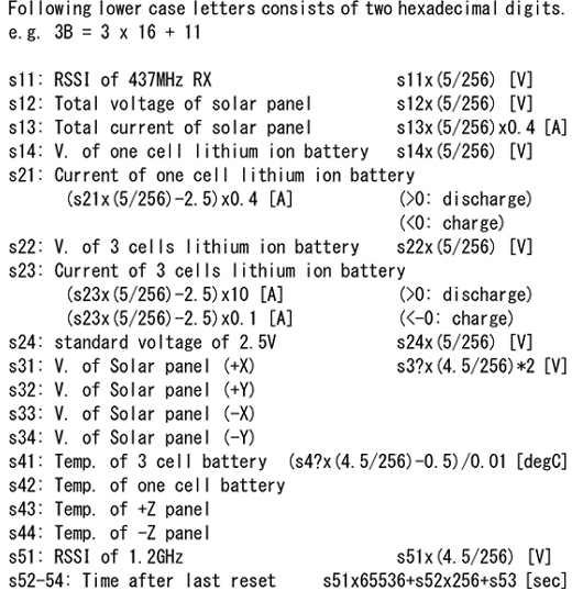
hi de niwaka japan s1 ef 03 00 ba  s2 88 da 81 81  s3 01 00 01 00  s4 1f 21 1c 1b  s5 1a 00 3b 0e
hi de niwaka japan s1 f0 02 00 ba  s2 89 da 81 81  s3 01 00 01 00  s4 1e 20 1b 1a  s5 1f 00 3b ab

---------------------------------------
FITSAT-1 NIWAKA Downlink CW Code
---------------------------------------
-------S1------
S-mater of 437MHz RX               :4,67[V]
Total Voltage of Solar cells       :0,06[V]
Total Current of Solar Cells       :0[mA]
Voltage of single cell battery     :3,63[V]
-------S2------
Current of single cell battery     :62,5[mA]
Voltage of 3 series battery        :12,77[V]
Current of 3 series battery        :0,02[mA]
Voltage of 2.5V reference          :2,52[V]
-------S3------
Voltage of Solar cell + X          :0,04[V]
Voltage of Solar cell + Y          :0[V]
Voltage of Solar cell - X          :0,04[V]
Voltage of Solar cell - Y          :0[V]
-------S4------
Temperature of 3 series battery    :  4,49[?]
Temperature of single cell battery :  8,01[?]
Temperature of +Z side             :  -0,78[?]
Temperature of –Z side             :  -2,54[?]
-------S5------
S-meter of 1.2GHz RX                :0,46[V]
------Timestamp-----
0day 4hour 11min 58sec
04.10.2012, 19:54 UTC (low 6 deg elevation pass in eclipse)
QSL-Karte
